
Pulse Induction Metal Detector
Several years ago, I built a metal detector based on the pulse induction principle. The design is based on the Hammerhead by Carl Moreland. I highly recomend the website geotech1.com, on which the Hammerhead and many other metal detector projects can be found, from very simple ones to highly advanced ones.
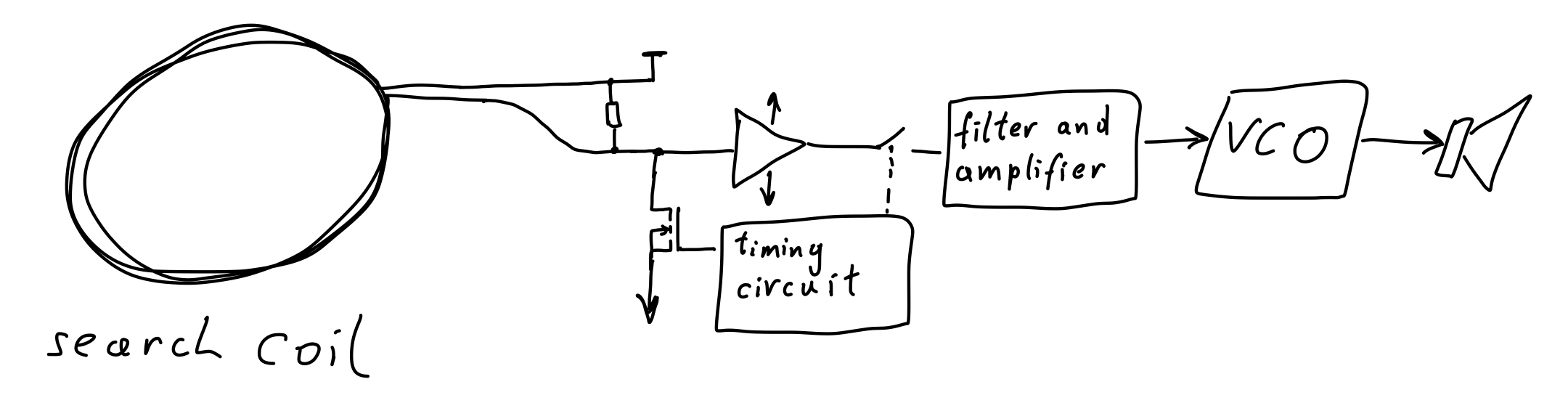
Metal detectors usually rely on either the frequency shift principle, the induction balance principle or the pulse induction principle. The principle, on which the metal detector presented in this article is based on, is the pulse induction principle. It uses a single coil. Periodically, a pulse of current is sent through the coil. The presence of metal influences the rate at which the current pulse decays, which is detected by amplifying and filtering a section of the decaying current pulse. A block diagram of a typical pulse induction metal detector setup can be seen below.
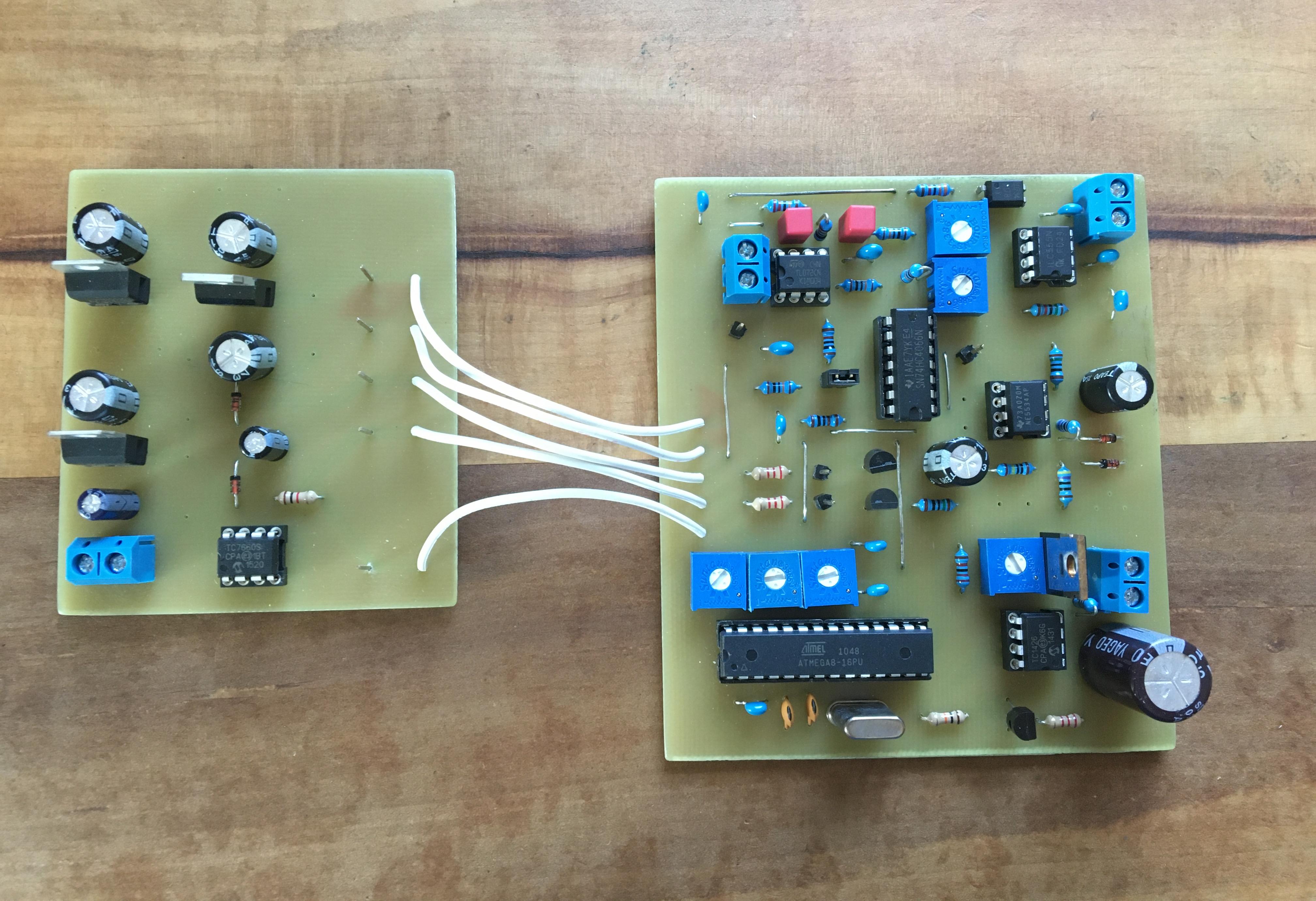
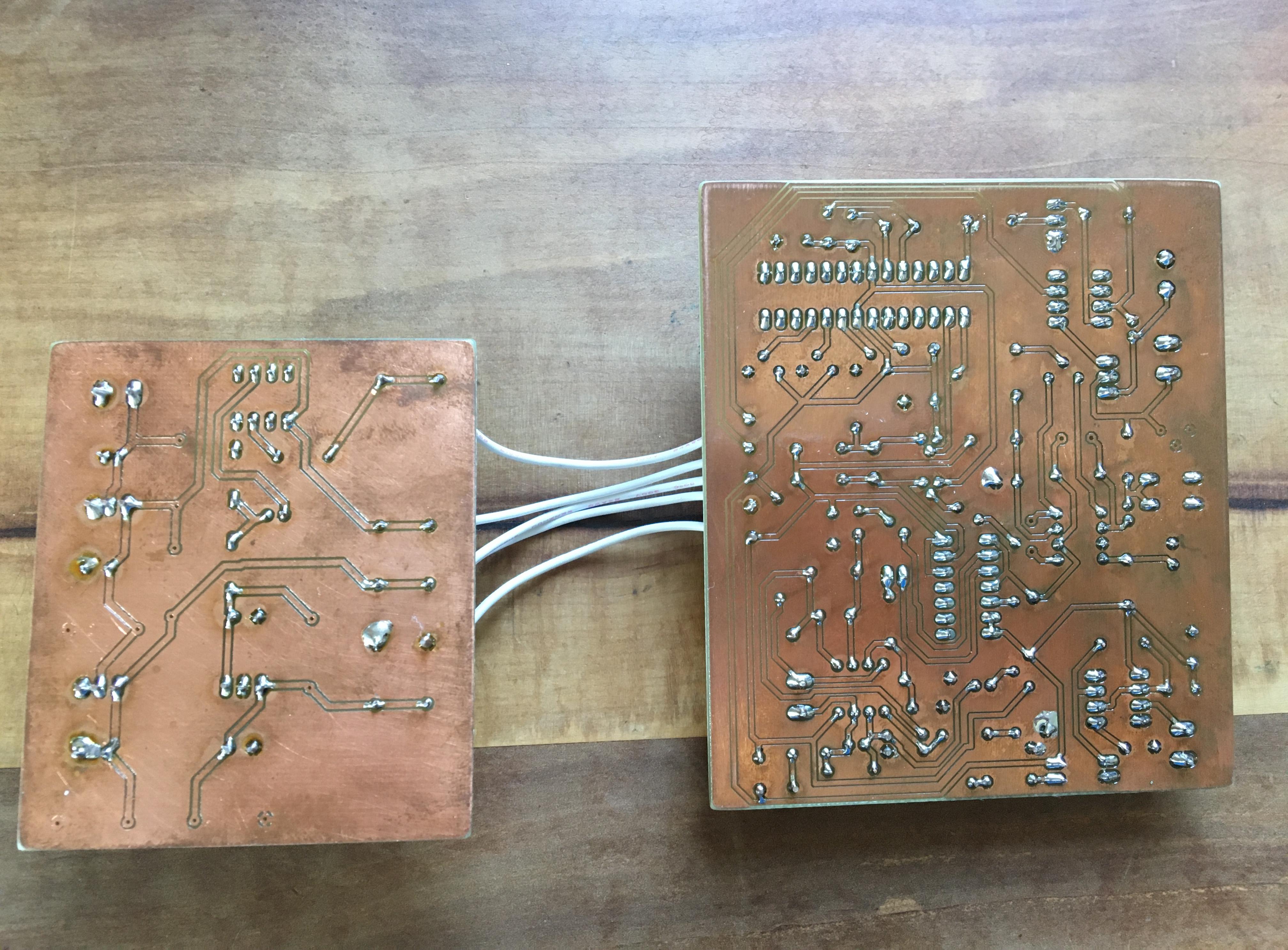
As mentioned, the design is based on the Hammerhead, though I made some modifications. First, I replaced the timing circuitry, which in the original design is made up of a 555 timer and several 74HC221 monoflops, by an ATmega8 microcontroller, which simplifies the timing circuit significantly and allows for precise, reproducible timing. To adjust the timing, potentiometers are connected to analog inputs of the ATmega8. The range in which the timing can be adjusted can easily be adapted in software. Second, I used a slightly different VCO circuit for the audio output of the metal detector. The time I designed the PCB, I used the free version of Eagle, in which the board size is limited to \(10\times 8\,\mathrm{cm}\). Due to these space limitations, I had to split the circuit into two parts. The smaller PCB contains only the circuitry related to the power supply, the larger PCB contains the rest of the circuit. I milled the PCBs on a CNC, which needed quite some tweaking until the result was acceptable and I would not do this again. Instead, I would simply order them from one of the many PCB manufacturers who accept orders from hobbyists.
I do not provide gerber files for these PCBs, the design of them is by no means optimal. PCBs for the original Hammerhead are provided for through-hole parts as well as smd parts.
Operation
Consider again the pulse induction metal detector block diagram.
Periodically, the MOSFET is turned on for several micro seconds. During this time, a voltage is applied to the search coil and the current in the search coil rises up to a few amperes. When the MOSFET is turned off, the current through the coil keeps flowing through the resistor in parallel to the coil and decays exponentially. The resistor value has to be adjusted carefully such that no ringing due to parasitic capacitances occurs. The rate at which the current decays is influenced by the presence of metal near the search coil. Several micro seconds after the MOSFET has been turned off, the switch in the above block diagram (practically realized by a CD4066 bilateral switch ic) closes for several micro seconds and thus, a section of the decaying pulse enters a filter and amplifier circuit. In a nutshell, the section of the decaying pulse is integrated. A slowly decaying current pulse results in a larger output voltage of the integrator than a faster decaying pulse. (Practically, there is no integrator but rather a lowpass filter with very high gain and a very low cutoff frequency.) Presence of metal thus results in a higher output voltage of the integrator, which is made audible by the voltage controlled oscillator (VCO), the higher the voltage, the higher the pitch of the sound.
For adjusting the timing, the damping resistor value as well as several offsets, an oscilloscope is very useful. In the Hammerhead article, the calibration is explained in detail. There, you can also find oscilloscope waveforms of the relevant signals.
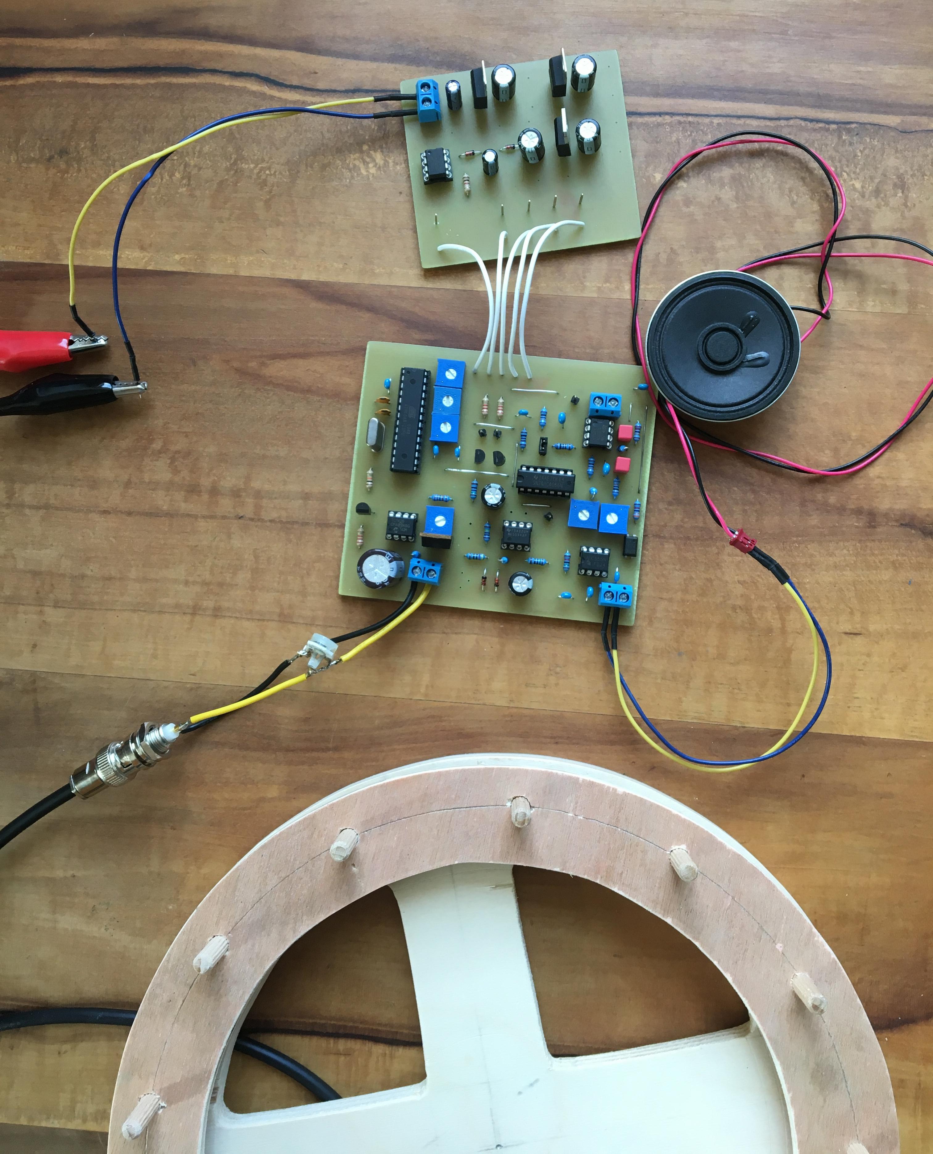
In the video below, you can see a test of my metal detector. A key ring is detected at approximately \(15\,\mathrm{cm}\), a 2€ coin at approximately \(10\,\mathrm{cm}\), a large microwave oven transformer is detected at approximately \(40\,\mathrm{cm}\) and a heavy rusty steal plate at close to \(60\,\mathrm{cm}\).
Other Metal Detector Principles
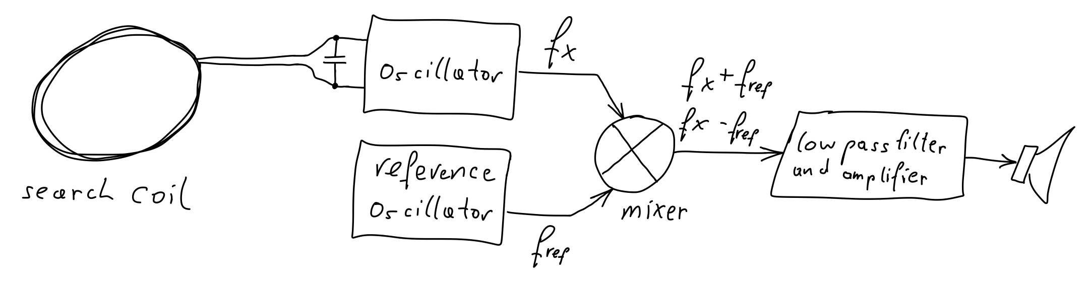
Some of the simplest metal detector designs are based on the frequency shift principle with the search coil being part of an LC oscillator, running typically at several ten to hundred \(\mathrm{kHz}\). The presence of metal influences the oscillation frequency, which is then detected – in the simplest case by mixing (i.e. multiplying) the signal from the oscillator with the signal of a reference oscillator, to convert it down into the audible frequency range. Crude mixing can be achieved by adding the signals of the two oscillators and sending their sum over a nonlinear element.
Another metal detection principle is the so-called induction balance principle. There, two coils are used which are arranged such that there is only weak coupling between them (usually two D-shaped coils that partly overlap, as in the figure below). The presence of metal influences the coupling of the coils, which is then detected (by driving one coil with a signal of a few \(\mathrm{kHz}\) and measuring the signal received by the other coil).