
CO2 Monitor
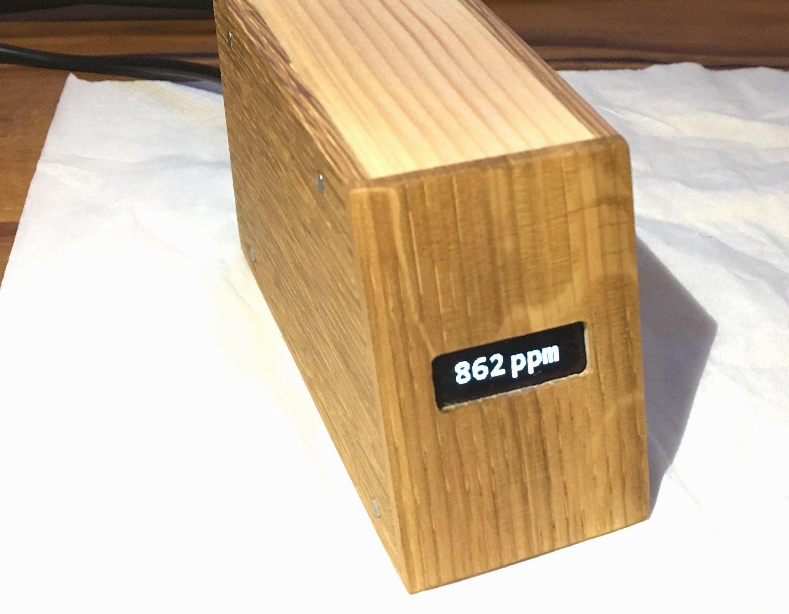
I built a device for monitoring the CO2 concentration of indoor air. It may be used e.g. in the office to remind one when it is time to ventilate the room.
Parts Used
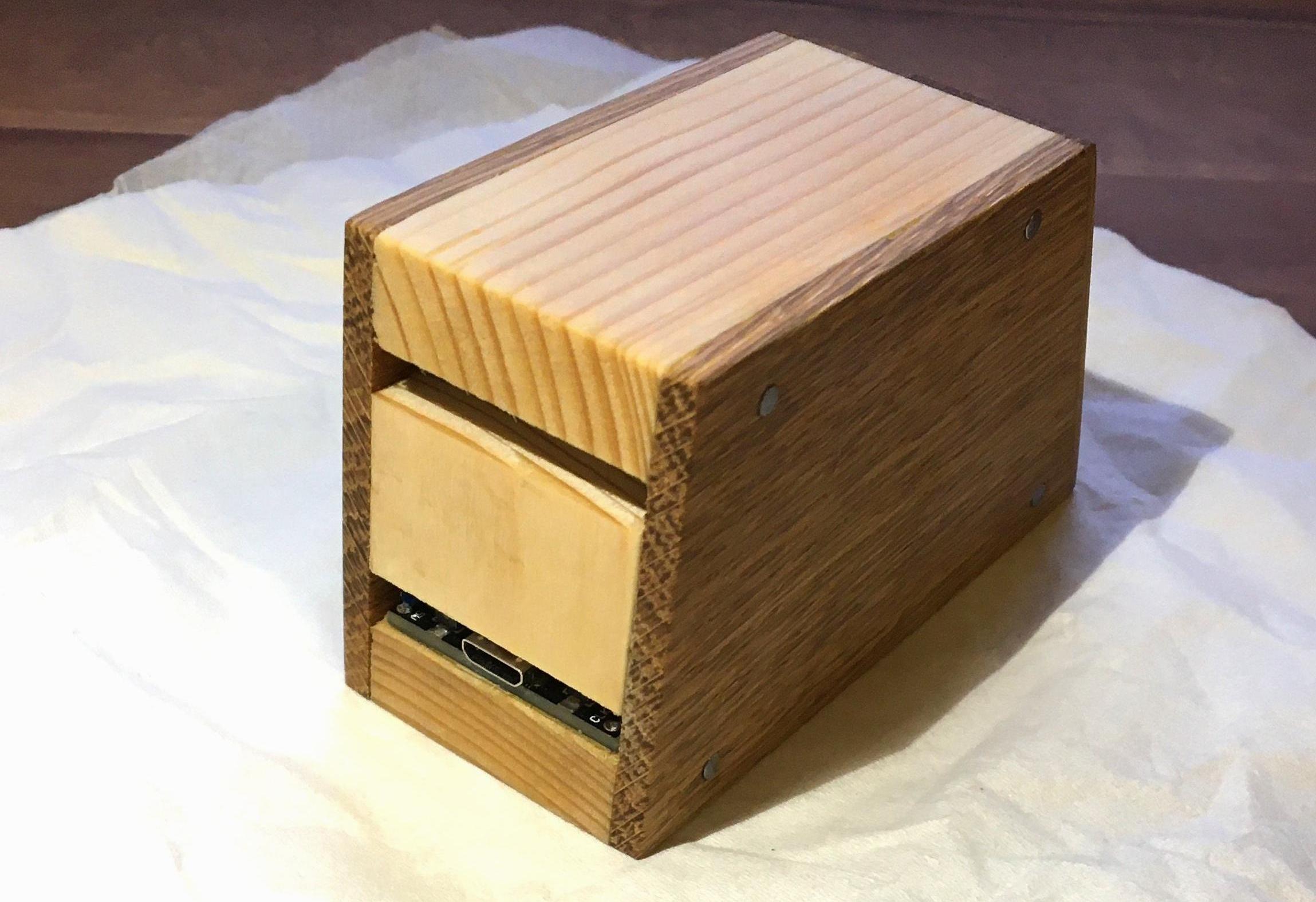
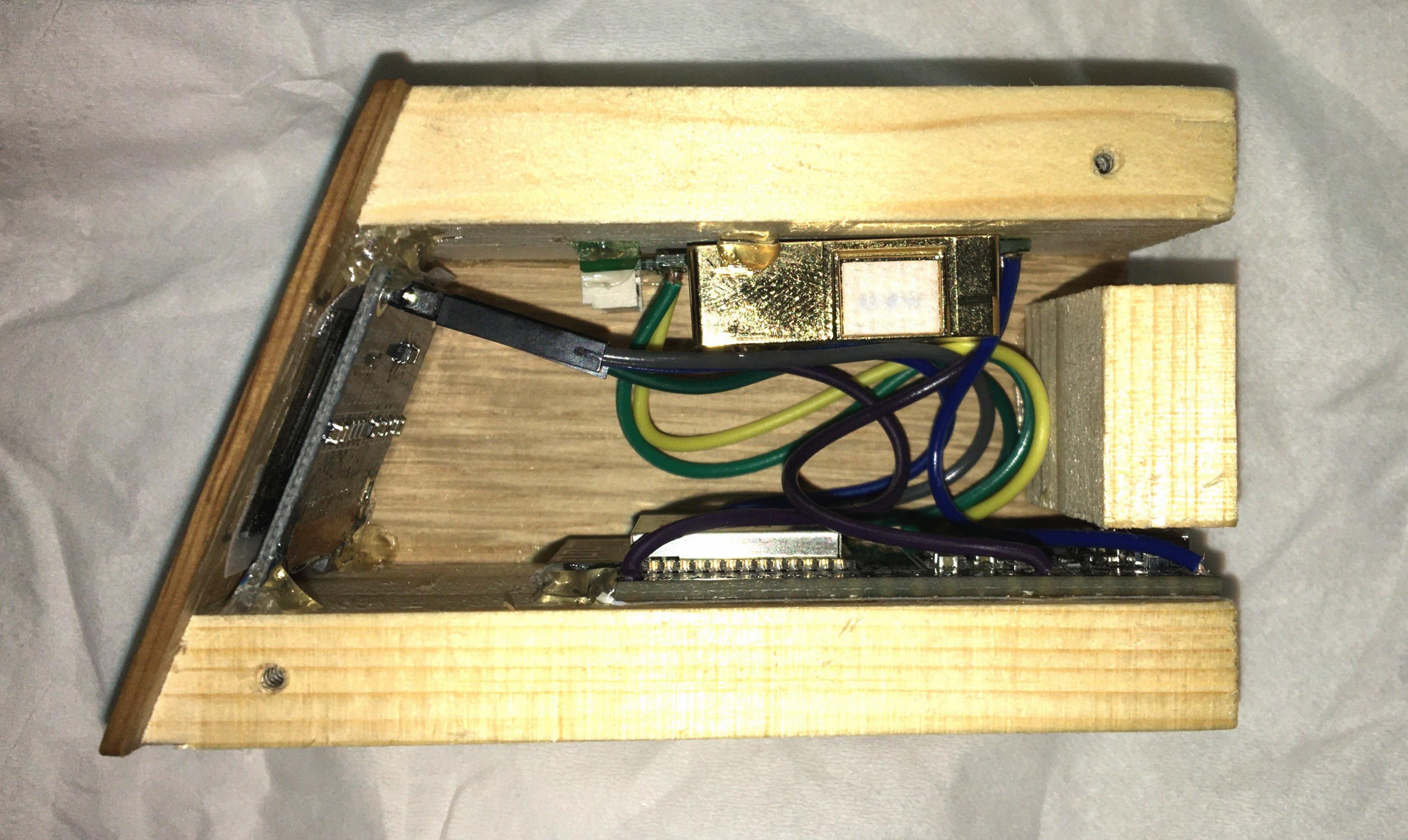
I used commonly available electronic parts for this build, the housing is a matter of some wood working and not discussed here. Electronically, the device consists of three main parts. As you can see in the figure above, on the bottom there is an ESP32 microcontroller board, namely the ESP32 Dev Kit C V4 by AZ-Delivery from which I removed the pre-soldered pin headers. On top, there is an MH-Z19B CO2 sensor. The CO2 concentration is displayed on a 128 x 64 pixels 0.96 inch OLED display, which can be seen on the left in the above figure.
The microcontroller board is held in place in the wooden housing with the help of double sided sticky tape. The sensor is held in place by some hot glue. Through the front window of the wooden housing, only part of the display is visible. Double sided sticky tape was used on the parts of the display which are covered by the front part of the housing, and additionally some hot glue came into use.
The device is powered via a micro USB cable plugged into the microcontroller board (via this cable the microcontroller is also programmed).
Wiring
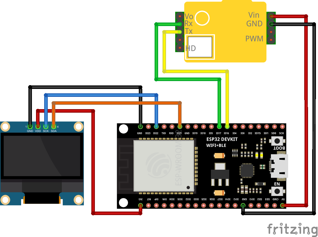
The sensor needs 5V and is supplied directly from the corresponding pins of the microcontroller board. The ESP32 is actually a 3.3V microcontroller. Fortunately, the interface level of the MH-Z19B pins for UART is 3.3V (though the MH-Z19B tolerates 5V on its UART pins). I did not find a fritzing model of the ESP32 Dev Kit C V4 by AZ-Delivery, but the ESP32 board which I used in the above wiring diagram has the same pinout as the ESP32 Dev Kit C V4.
Code
All the code can be found in the github repository https://github.com/conrad-gst/co2-monitor. The microcontroller is programmed in MicroPython. The microcontroller requests a measurement from the sensor every three seconds and updates the screen accordingly. The microcontroller and the sensor communicate via UART, whereas I2C is used for the communication between the microcontroller and the display. The main program running on the microcontroller is listed below.
main.py
1
2
3
4
5
6
7
8
9
10
11
12
13
14
15
16
17
18
19
20
21
22
23
24
25
26
27
28
29
30
31
32
33
34
35
36
37
38
39
40
41
42
43
44
45
46
from machine import Pin, SoftI2C
from time import sleep
import mhz19b
import ssd1306
import consolaB
import writer

mhz_sensor = mhz19b.MHZ19BSensor(rx_sensor=17, tx_sensor=16)
# connect RX and TX of the sensor to GPIO17 and GPIO16 of the microcontroller

i2c = SoftI2C(scl=Pin(22), sda=Pin(21))
display_width = 128
display_height = 64
display = ssd1306.SSD1306_I2C(display_width, display_height, i2c)
display.contrast(100)
font_writer = writer.Writer(display, consolaB)

sleep(1)
n = 0
while True:
    try:
        co2 = mhz_sensor.measure()
        if co2 == None:
            raise Exception()

        display.fill(0)

        text1 = "{co2:d}".format(co2=co2)
        text2 = "ppm"
        text1_width = font_writer.stringlen(text1)
        text2_width = font_writer.stringlen(text2)
        space = 4 # space between text1 and text2 in pixel
        text_width = text1_width + space + text2_width
        font_writer.set_textpos(int((display_width - text_width) / 2), 20)
        font_writer.printstring(text1)
        font_writer.set_textpos(int((display_width - text_width) / 2 +
        text1_width + space), 20)
        font_writer.printstring(text2)
        display.show()
        sleep(3)
    except Exception as e:
        display.fill(0)
        display.text("Reading sensor",0,20)
        display.text("failed.",0,35)
        display.show()
        sleep(0.5)
In line 8 of the main program, the class MHZ19BSensor is instantiated, i.e. a sensor object is created. The constructor of this class takes the microcontroller pins to which the RX and the TX pins of the sensor are connected (compare with the wiring diagram above). In line 11, an object of the class SoftI2C (which comes with the machine module) is created (instead of pin numbers for scl (serial clock) and sda (serial data), Pin objects have to be provided here). This I2C object is needed in line 14, where the class SSD1306_I2C is instantiated (SSD1306 is a very common driver chip for OLED displays, mine uses this chip). Finally, the Writer class is instantiated. I use this class in order to be able to use consolasB as font (the standard font coming with the SSD1306 class is very small). Then, in line 20, an endless loop is entered. A measurement is taken in line 22, in line 26, the display is cleared. The purpose of lines 28 to 38 is to display the new sensor reading centered on the display. After a delay of three seconds, the whole cycle repeats.
The following code for communicating with the MH-Z19B sensor is based on https://github.com/artem-smotrakov/esp32-weather-google-sheets/blob/master/src/weather.py by artem-smotrakov (see also https://github.com/carlesfg/MicroPython/blob/CO2-Sensor/MHZ19B.py).
mhz19b.py
1
2
3
4
5
6
7
8
9
10
11
12
13
14
15
16
17
18
19
20
21
22
23
24
25
26
27
28
29
30
31
32
33
34
35
36
37
38
39
40
41
42
import time
from machine import UART

class MHZ19BSensor:

    # constructor
    def __init__(self, rx_sensor, tx_sensor):
        self.uart = UART(2, baudrate=9600, rx=tx_sensor, tx=rx_sensor,
        bits=8, parity=None, stop=1, timeout = 1000, timeout_char = 1000)
        self.data = bytearray(9)
        self.request_data = b'\xff\x01\x86\x00\x00\x00\x00\x00\x79'
        self.measure() # dummy reading since the first reading usually fails

    # measure CO2
    def measure(self):
        # send a read command to the sensor
        self.uart.write(self.request_data)

        # read and validate the data
        self.uart.readinto(self.data,9)
        if self.is_valid():
            co2 = (self.data[2] << 8) + self.data[3]
            return co2
        else:
            self.reset()
            return None

    # check data returned by the sensor
    def is_valid(self):
        if self.data[0] != 0xFF or self.data[1] != 0x86:
            return False
        i = 1
        checksum = 0x00
        while i < 8:
            checksum += self.data[i] % 256
            i += 1
        checksum = ~checksum & 0xFF
        checksum += 1
        return checksum == self.data[8]

    def reset(self):
        self.uart.read(self.uart.any())
In the constructor of this class, an UART object is created. Furthermore, the bytearray self.data is declared, which is used as a buffer for data received via UART from the sensor. According to the datasheet of the MH-Z19B, in order to request a reading from the sensor, a total of 9 Bytes has to be sent namely \xff\x01\x86\x00\x00\x00\x00\x00\x79, which is stored in self.request_data. The sensor responds with 9 Bytes, the actual data, i.e. the CO2 concentration is contained in Byte2 and Byte3 and calculated via concentration = Byte2 * 256 + Byte3 (in the above code, this calculation is performed in line 22 where the multiplication by 256 is replaced by a bit-shift). Byte8 is a checksum, this Byte must coincide with the checksum calculated from the remaining Bytes in the lines 33 to 38. (In the datasheet, a snippet of C-code which demonstrates the calculation of the checksum is provided.)
The sensor accepts several other commands, e.g. for calibrating the sensor. These commands are not used here. The sensor readings are reasonable after all. Outdoors, it reads about 400 ppm. Ideally, indoor air should not exceed a CO2 concentration of 1000 ppm. Since the main purpose of this device is to remind one when it is time to ventilate the room, it does not really matter if readings are off by e.g. 50 ppm.
For controlling the OLED display, an ssd1306 library from https://github.com/micropython/micropython is used. Since the display is only used for displaying the current CO2 concentration, I wanted a large font which is well readable also from some distance. Therefore, I used the micropython-font-to-py project by peterhinch. In this project, a command line tool called font_to_py.py is provided, which is capable of converting a font file (.ttf-file or .otf-file, such files can be downloaded for free for a lot of fonts) into a python file which can then be used in conjunction with writer.py to display text in this font. I have used CONSOLAB.ttf which I got from https://www.fonts100.com/font+21195_Consolas.html and specified the height to be 25 pixels. The command line call for producing the corresponding micropython file is as follows:
python3 font_to_py.py -x CONSOLAB.ttf 25 consolaB.pyAs mentioned above, all the code can be cloned from my github repository https://github.com/conrad-gst/co2-monitor.