
Balancing Robot
I built a little self balancing robot a while back. The project never really left the prototype stage, though it worked to some extent and I may revisit this topic in the future. I do not provide building instructions or source code here. If you plan to build something similar, I recommend checking out the balancing robot project on Brokking.net.
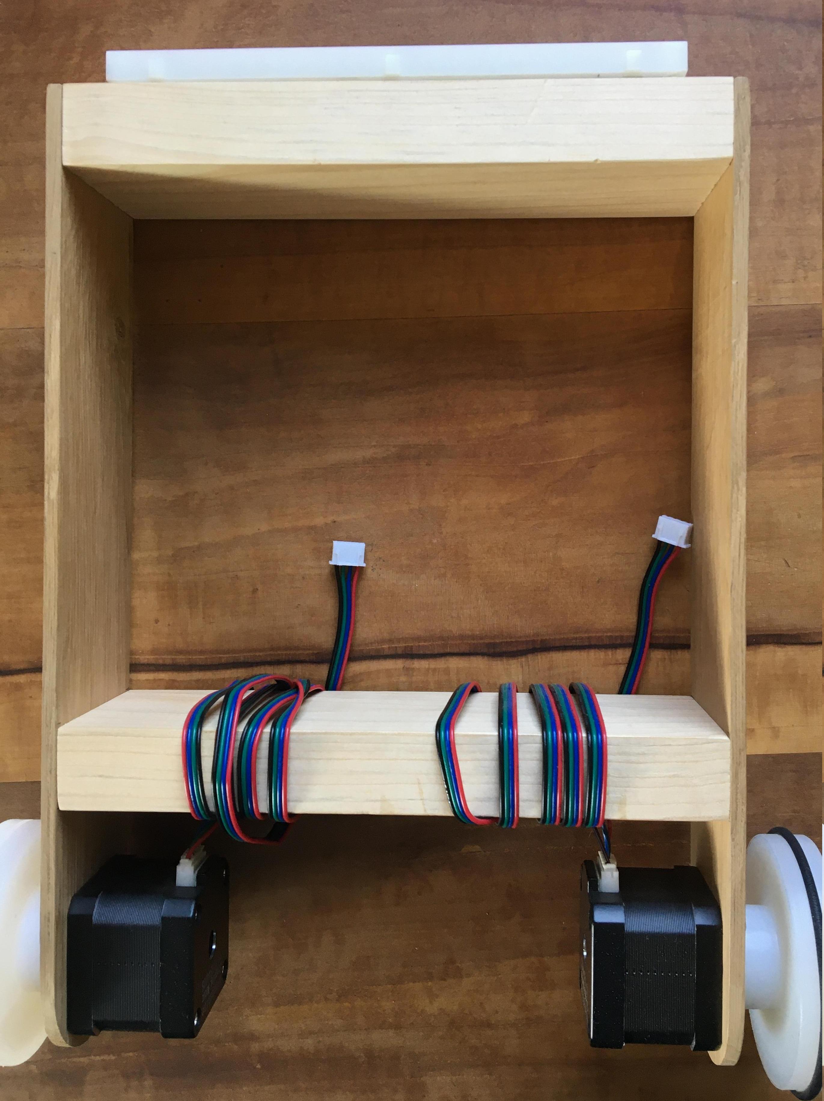
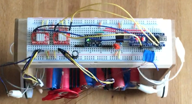
I used an Arduino Nano in this project, which can be seen on the right side in the above figure. The microcontroller reads gyroscope and accelerometer data from an MPU6050 IMU breakout board. Gyroscope and accelerometer data are used to estimate the tilt angle of the robot by means of a complementary filter. The wheels of the robot are directly mounted onto two stepper motors. The stepper motors are connected to two stepper motor driver boards based on the A4988 microstepping driver. The robot is controlled by a wired remote control featuring four buttons – forwards, backwards, turn left, turn right. I planned to use the common nRF24L01 transceiver modules for true remote control, but unfortunately, the project never left the crude prototyping stage documented here. The robot is powered by 6 Li-ion cells in a 3S2P configuration (further cells in series would be beneficial for higher acceleration and higher top speed, the used drivers could actually handle up to 35 V).
For preventing the robot from tipping over and to make it move, the (rather heuristic) control strategy depicted in the block diagram below was used.
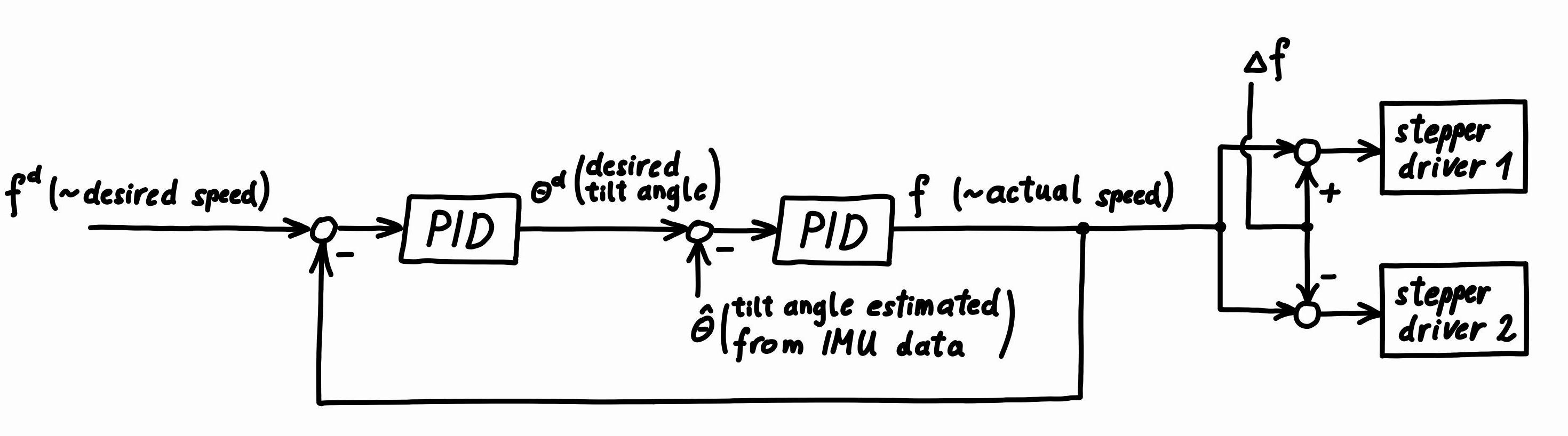
Set point is the desired speed (since stepper motors are used, the speed of the robot is directly proportional to the step frequency which the stepper drivers receive – at least as long as the stepper motors do not lose steps). Purpose of the first PID controller is to control the speed of the robot. The output of this controller is the set point for the inner control-loop, whose purpose it is to control the tilt angle of the robot.
The step frequencies entering the two stepper drivers differ by (twice) the signal \(\Delta f\), which makes the robot turn.
When no button is pressed on the crude four button wired remote control, the input signals \(f^d\) and \(\Delta f\) are zero. Pressing buttons means full forwards or backwards, resp. full turn to the left or to the right, i.e. only step inputs are possible with this crude remote control. These step inputs are digitally low-pass filtered in order to achieve a somewhat smooth driving behavior. With a proper remote control, the input signals would come from joysticks.
I intend to revisit this topic and build a balancing robot setup which allows me to implement and test different model based control strategies instead of just the heuristic approach taken here.