ZVS Circuit
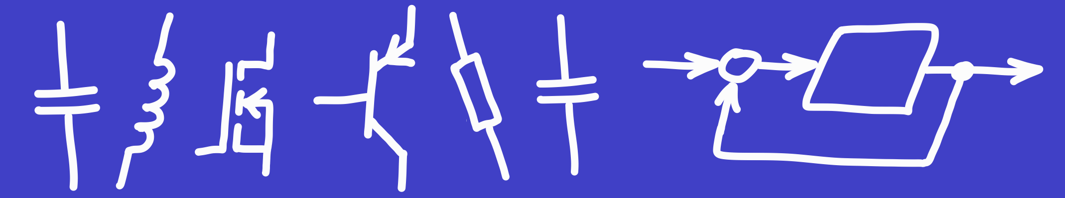
ZVS stands for Zero Voltage Switching. It is a technique used in power electronic circuits for minimizing switching losses by switching the power transistors only when the voltage across them is zero. In the hobbyist community, a particular power oscillator circuit is associated with the term ZVS, namely the oscillator circuit in the figure below.
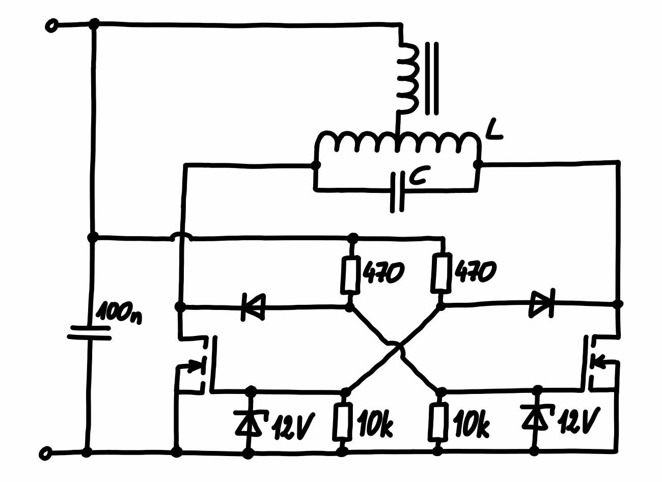
It is an LC oscillator and the switching of the MOSFETs indeed occurs when there is close to no voltage across them (this can easily verified by setting up e.g. an LTspice simulation). A practical realization of this circuit can be seen in the figure below.
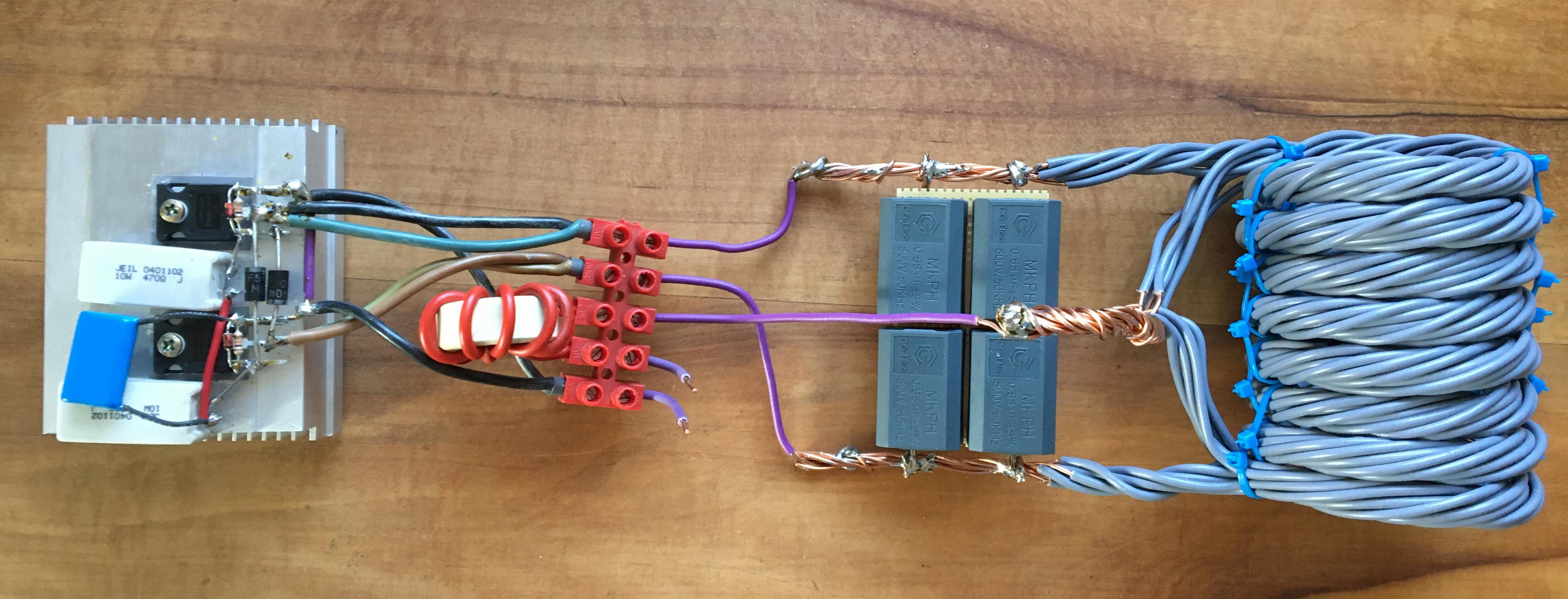
I built it with IRFP260N power MOSFETs, MUR460 diodes and the used \(470\,\Omega\) resistors are rated for \(10\,\mathrm{W}\). The Zener diodes are standard \(12\,\mathrm{V}\), \(1\,\mathrm{W}\) ones and the \(10\,\mathrm{k\Omega}\) resistors are rated for \(0.25\,\mathrm{W}\). I made the choke, i.e. the inductor at the top in the above schematic, from an unknown ferrite or iron powder core. The capacitor of the LC tank circuit is made from four MKPH capacitors, each of them having a capacitance of \(0.68\,\mathrm{\mu F}\) and rated for \(800\,\mathrm{V}\) at \(50\,\mathrm{kHz}\) (I salvaged them from an induction stove top). The four capacitors are wired up in pairs of two in series and these pairs are wired in parallel, so the total capacitance is still \(0.68\,\mathrm{\mu F}\), but the stress is shard among all of them.
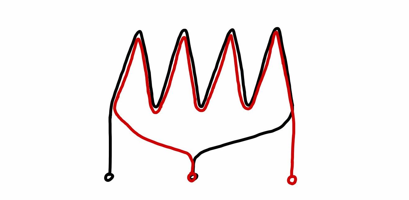
The coil of the tank circuit is made from \(1.5\,\mathrm{mm^2}\) home installation wire. Its construction is illustrated in the figure below, i.e. there are actually two coils overlaid for good magnetic coupling. The point where the two overlaid coils are connected forms the center tap of the complete coil. In the practical setup, each of the two overlaid coils consists itself of six separate strings of \(1.5\,\mathrm{mm^2}\) home installation wire. To make this coil, I first took twelve wires in parallel, twisted them together and wound them to a coil. Then, I selected six of these twelve wires to form one end of the coil. The other ends of these selected six wires form the center tap and were then connected to the remaining six wires, the ends of which form the other end of the coil. Several zip ties assure that the coil holds its shape.
So the coil has effectively \(16\) turns, a diameter of approximately \(60\,\mathrm{mm}\) and a length of approximately \(85\,\mathrm{mm}\). According to the online inductance calculator https://wetec.vrok.de/rechner/cspule.htm, this should give us an inductance of approximately \(8.1\,\mathrm{\mu H}\). Together with the \(0.68\,\mathrm{\mu F}\) tank capacitor, the resonance frequency follows as \(f_{res}=1/(2\pi\sqrt{LC})\approx 68\,\mathrm{kHz}\).
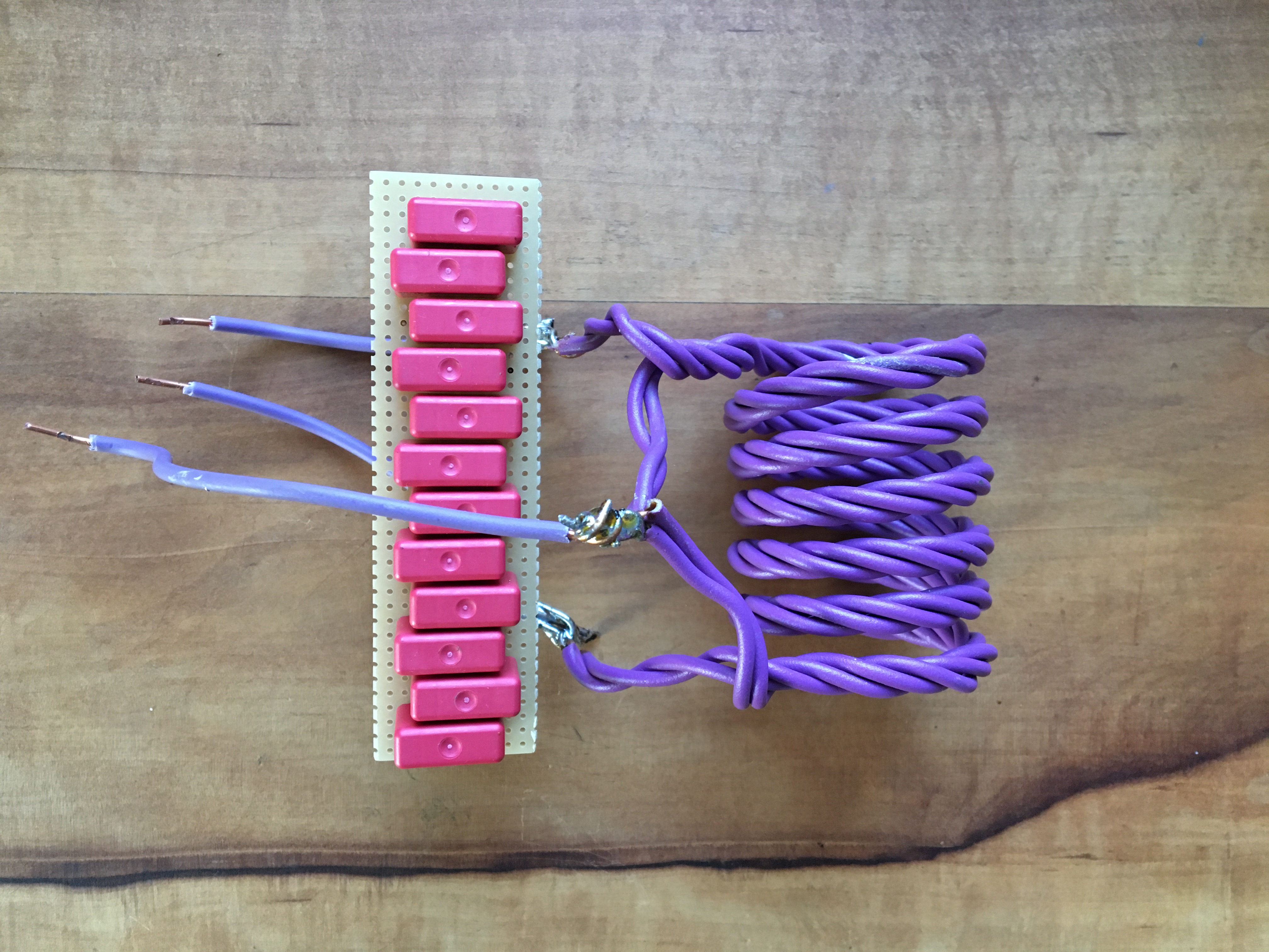
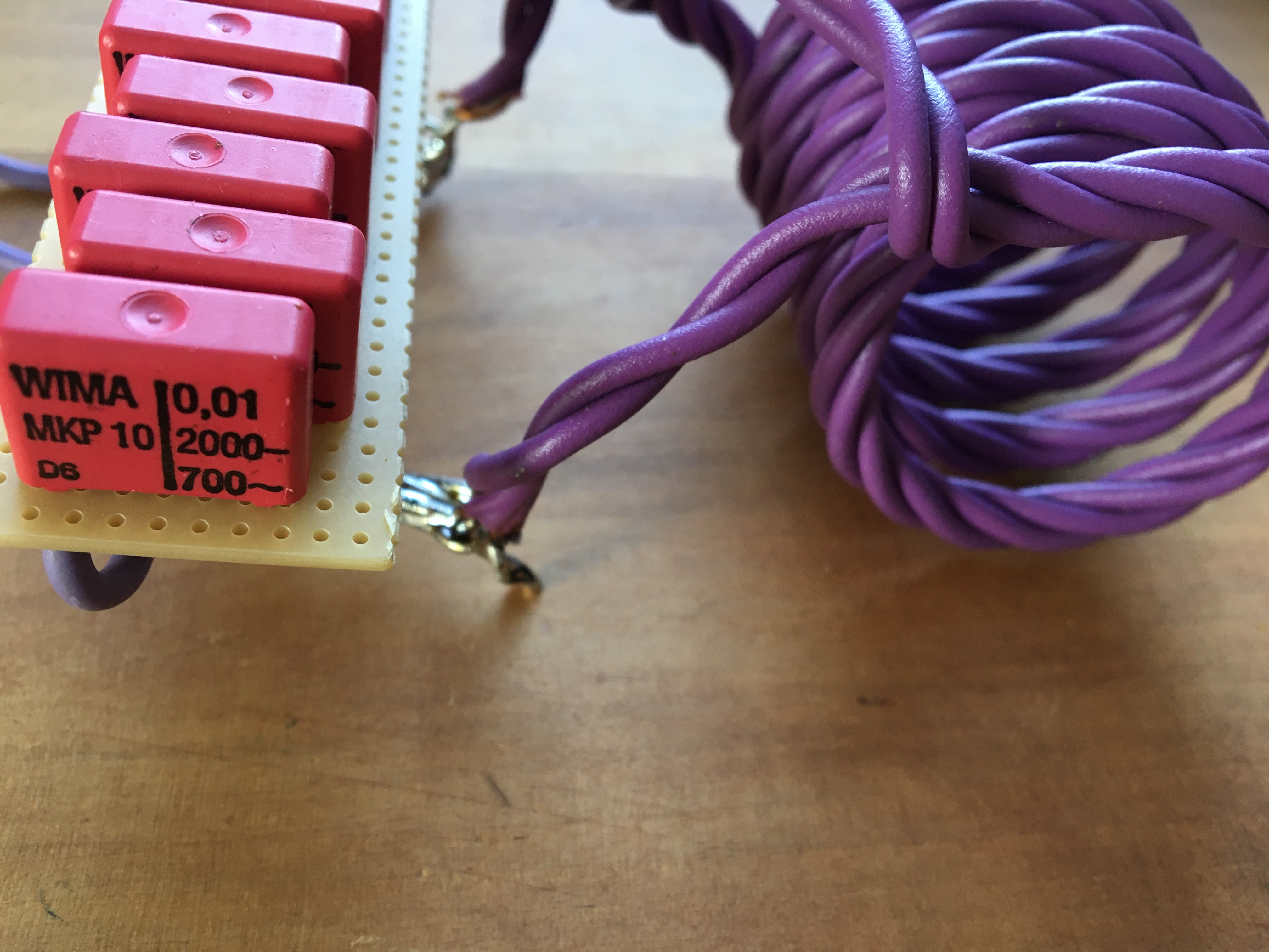
The circuit is built such that the tank circuit can easily be replaced. Another tank circuit can be seen in the two figures below. It has a capacitance of \(120\,\mathrm{nF}\) and the coils inductance, according to the online calculator, is \(3.4\,\mathrm{\mu H}\), resulting in \(f_{res}=249.2\,\mathrm{kHz}\).
Test Results
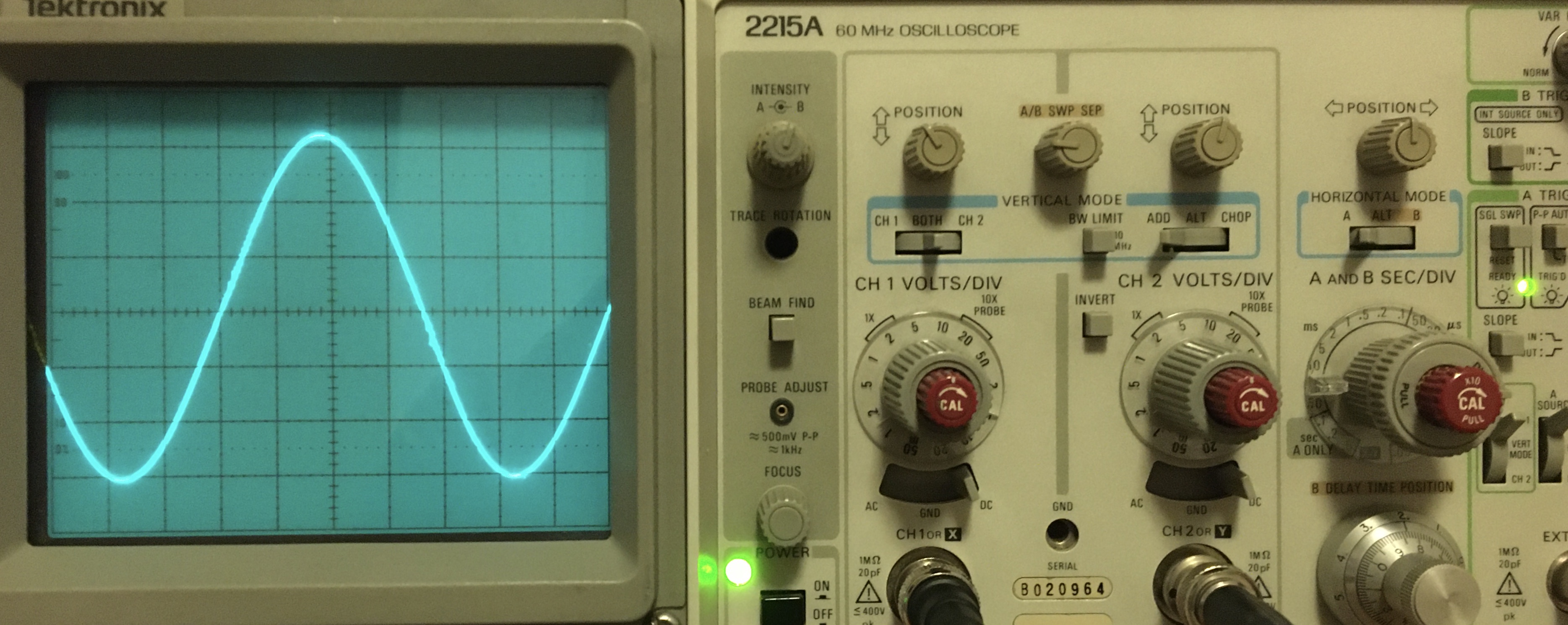
With both tank circuits, a supply voltage of \(12\,\mathrm{V}\) suffices for reliable oscillation. With my old analog Tektronix 2215A oscilloscope, I measured an oscillation frequency of \(71.4\,\mathrm{kHz}\) with the first tank circuit, and \(250.0\,\mathrm{kHz}\) with the second one. The oscillation frequency varies only very slightly with the supply voltage.
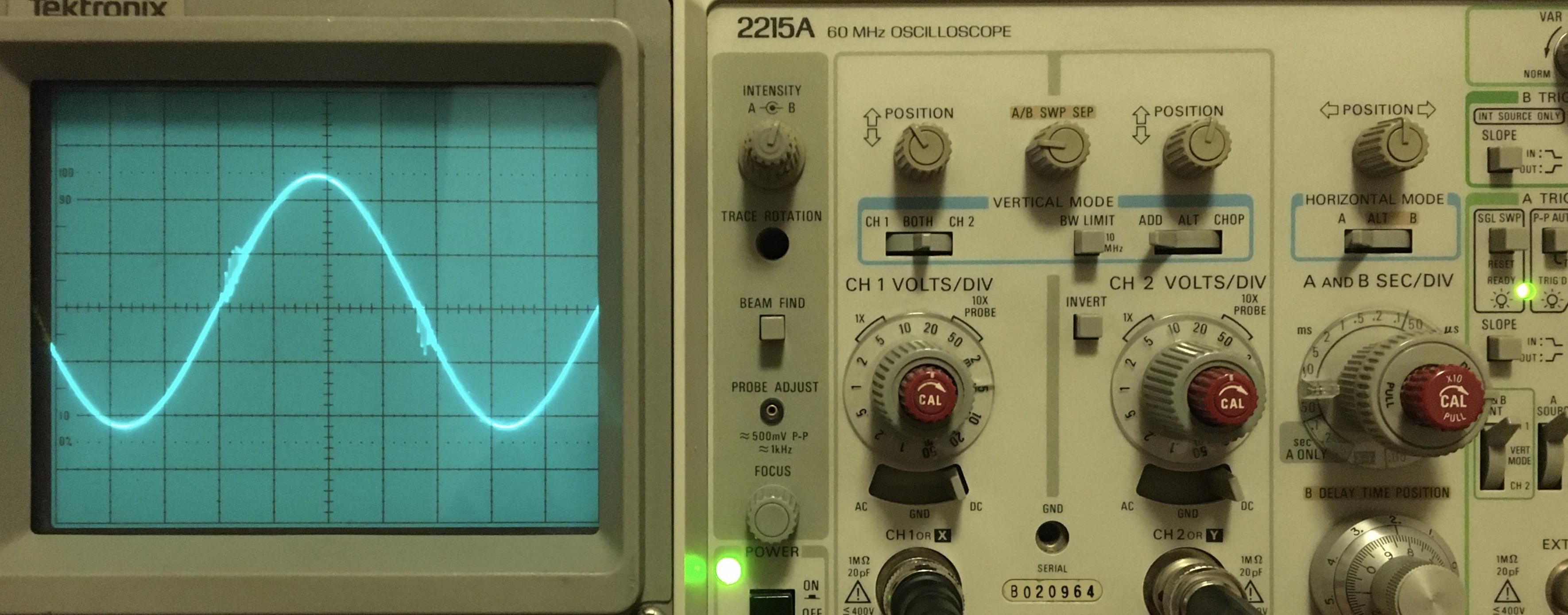
In the image below, the voltage across the tank circuit (the first tank circuit, i.e. the one with the lower resonance frequency) for a supply voltage of \(20\,\mathrm{V}\) resp. \(37\,\mathrm{V}\) can be seen. The current drawn from the power supply is \(0.77\,\mathrm{A}\) resp. \(1.45\,\mathrm{A}\), corresponding to a power dissipation of \(15.4\,\mathrm{W}\) resp. \(53.7\,\mathrm{W}\). Neither the MOSFETs nor the capacitors heat up significantly, so it seem like most of the power is dissipated in the coil, which indeed heats up a lot. The voltage across the tank circuit seems to have a relatively clean sinusoid shape, with slight distortions at the zero crossings. The amplitude is approximately \(63\,\mathrm{V}\), resp. \(115\,\mathrm{V}\), from which the amplitude of the current flowing in the tank circuit follows as approximately \(18\,\mathrm{A}\) resp. \(33\,\mathrm{A}\).
With the second tank circuit, the voltage waveform is more distorted at the zero crossings. The MOSFETs also heat up much more, but the coil is again the part which heats up the most.
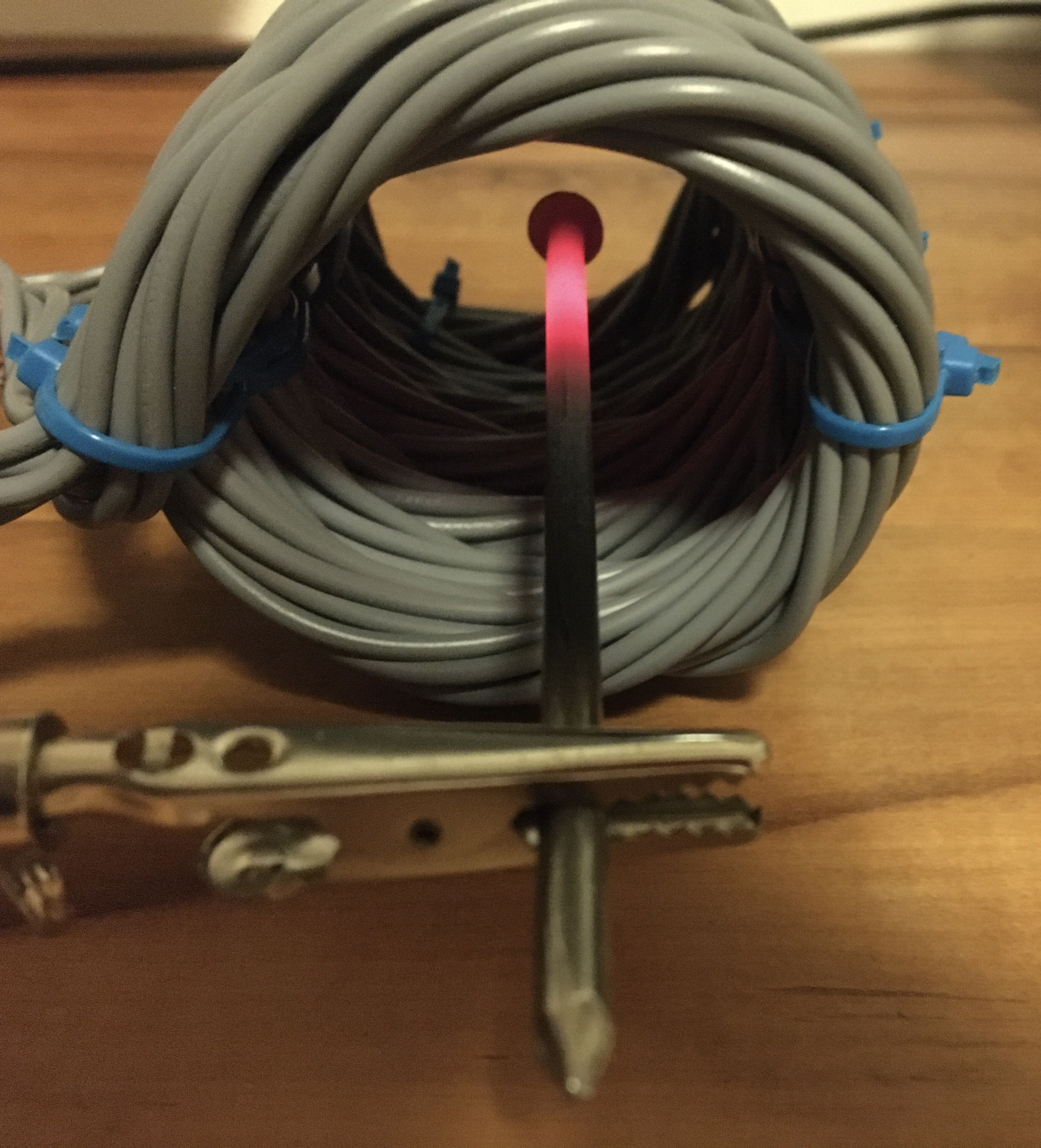
When putting a metal object into the coil, the current drawn from the power supply rises and the metal object heats up due to eddy currents induced in it by the alternating magnetic field of the coil. In the figure below, you can see a \(4.1\,\mathrm{mm}\) diameter nail heated up until glowing brightly. Since the power supply used in these tests can only deliver \(3.2\,\mathrm{A}\), I was limited to small metal objects. This limit is already reached with the \(4.1\,\mathrm{mm}\) nail put only half way into the coil. The MOSFETs and the capacitors still did not heat up significantly. The amplitude of the voltage across the tank circuit and the oscillation frequency were hardly affected by the nail in the coil.
With the second tank circuit, I was not able to heat the nail up until glowing. The coil got too hot too quickly.