
Vacuum Tube Amplifier
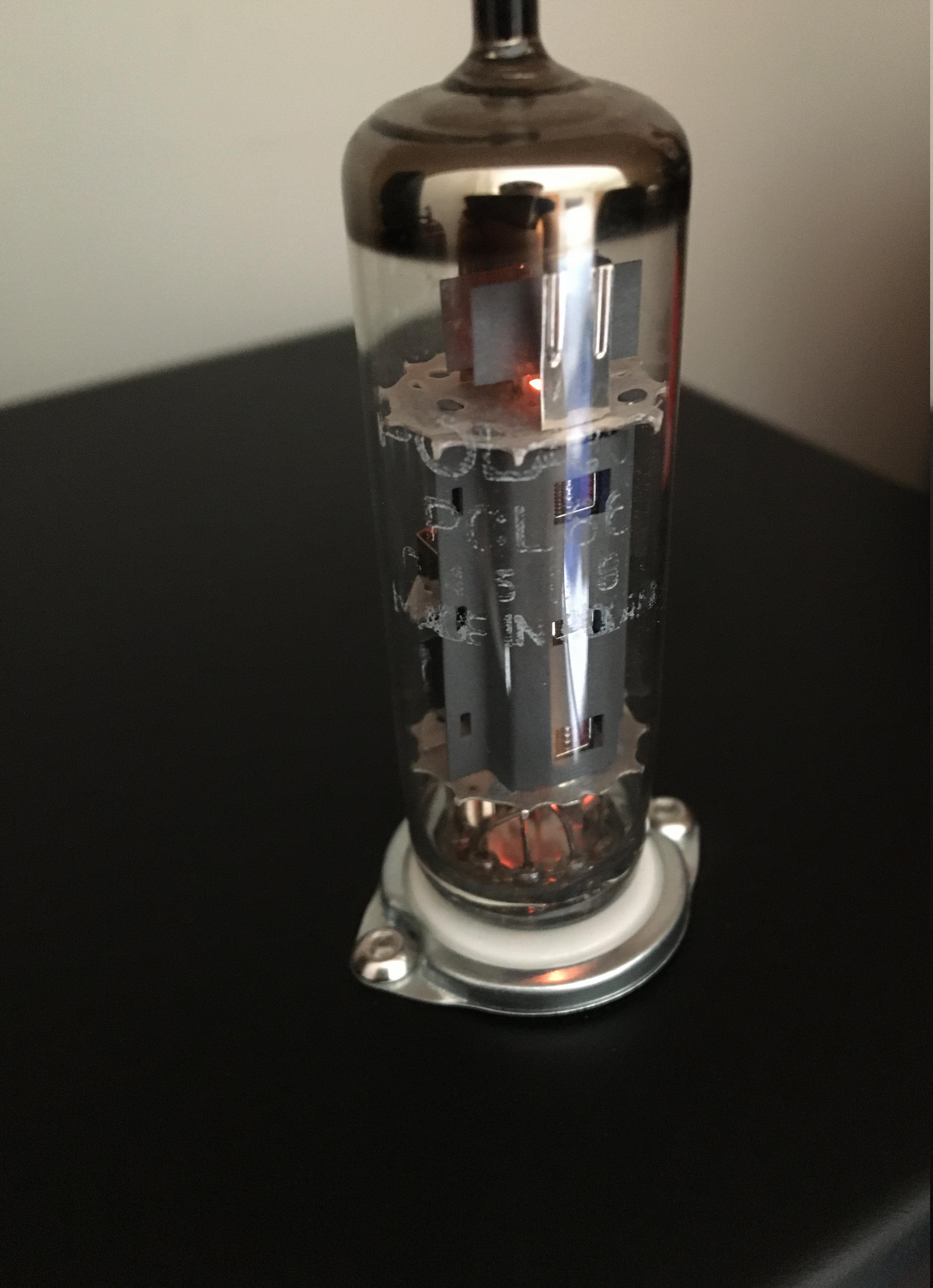
I built a vacuum tube amplifier based on the PCL86. The PCL86 contains a triode, intended as pre-amplifier and a pentode, intended as output tube, in one package. This tube is still widely available and relatively cheap. Each of the two channels of the amplifier uses one PCL86 tube.
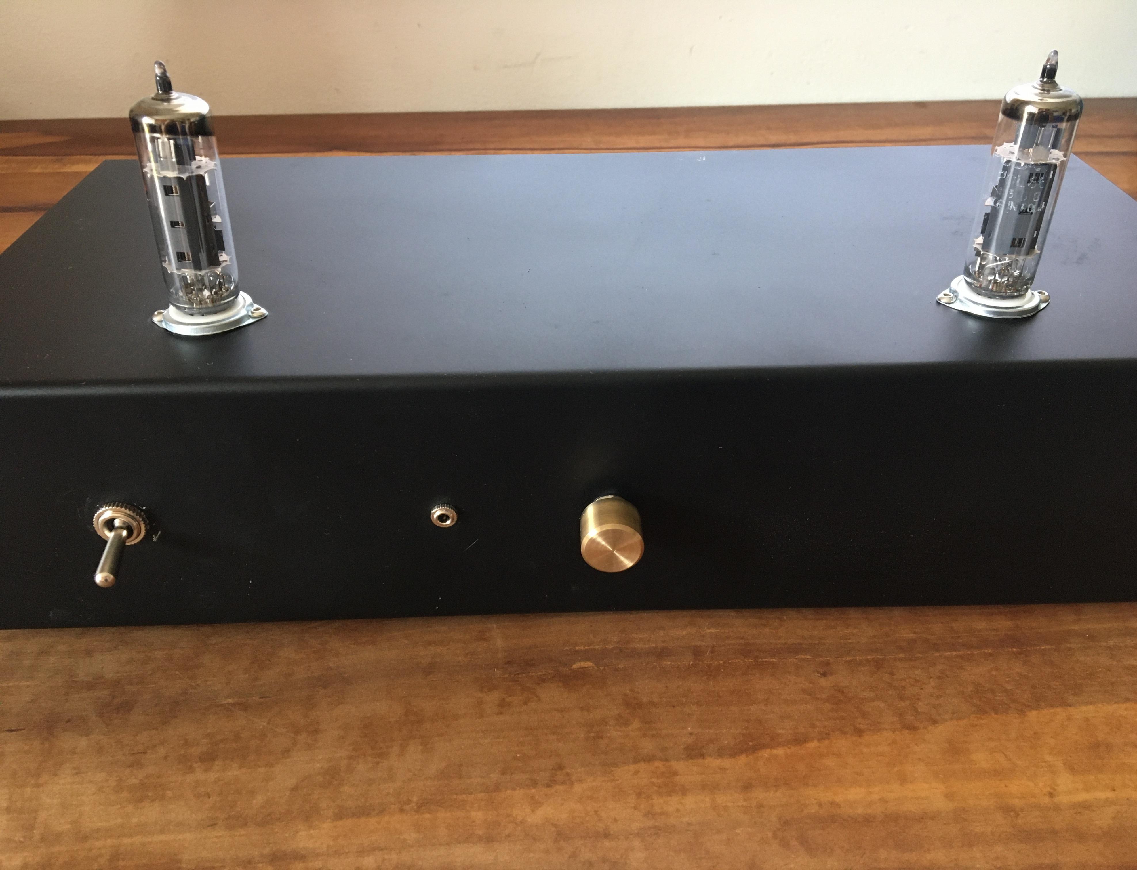
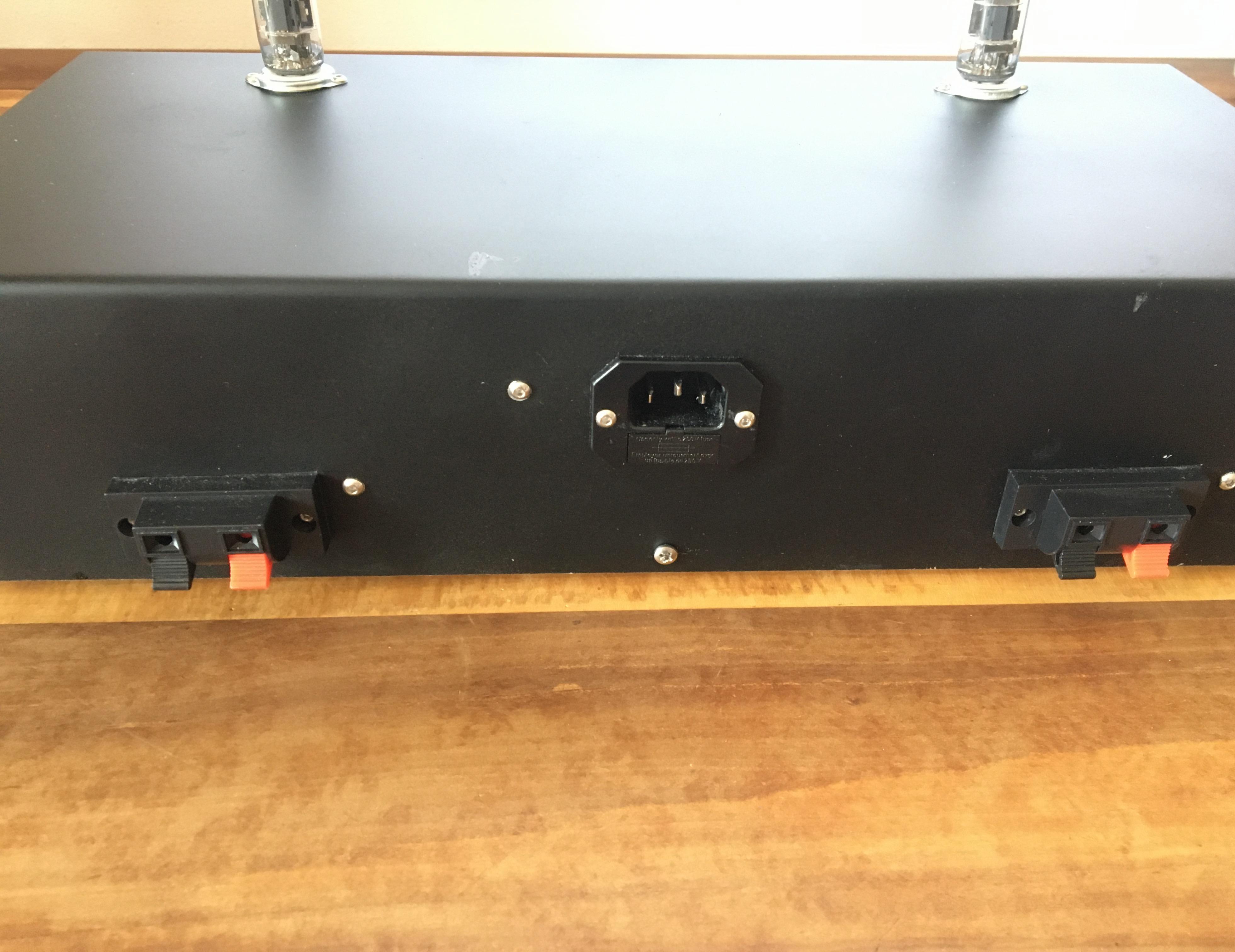
I kept the design minimalistic. On the front panel of the amplifier, you can see an ON/OFF-switch, a standard \(3.5\,\mathrm{mm}\) audio jack for the audio input and a potentiometer for volume control. The knob of the potentiometer is a custom made brass part which I machined on a lathe. On the back side, there is a mains socket and two speaker terminals - one for the left channel and one for the right channel.
Mechanical Construction
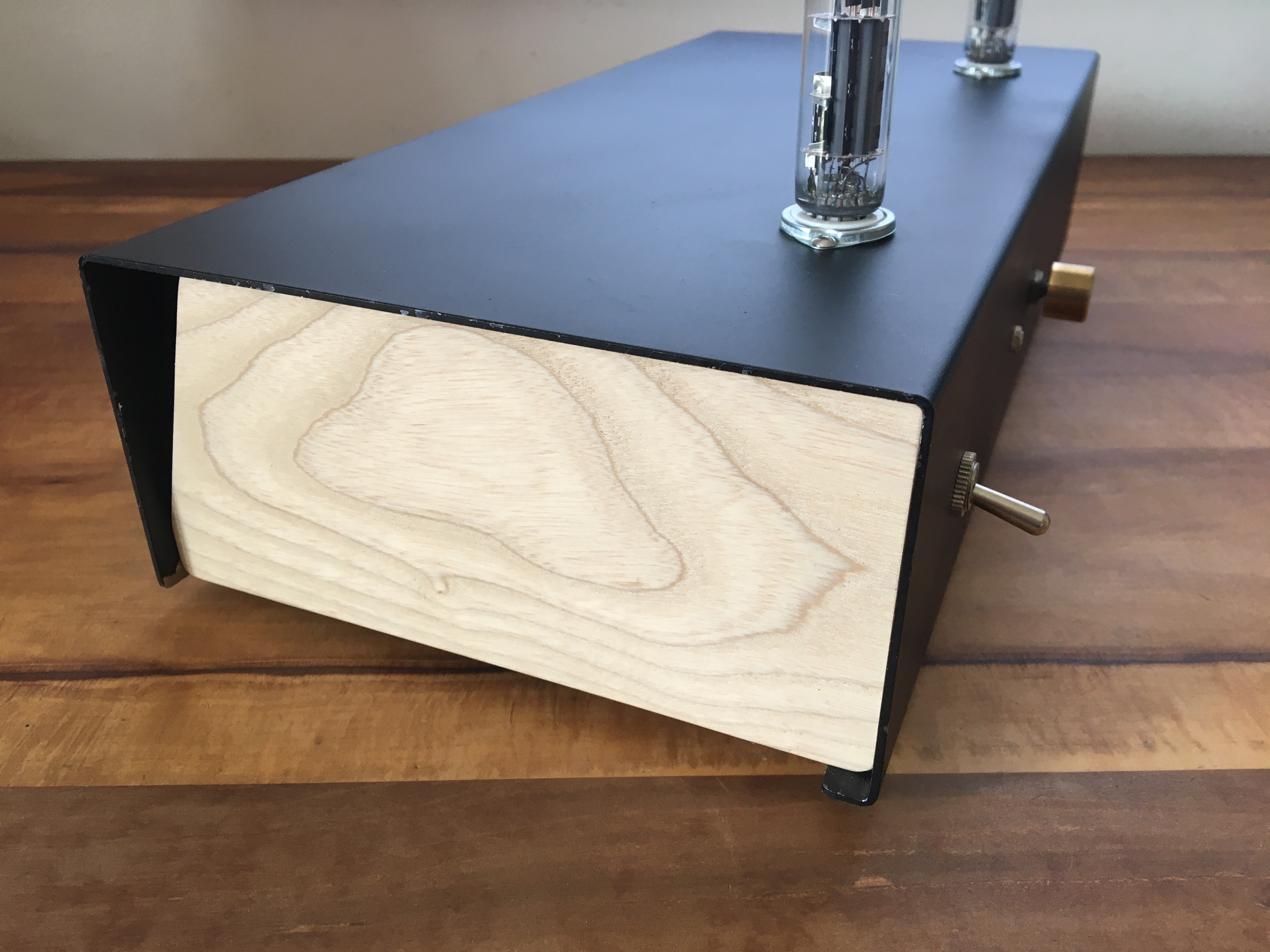
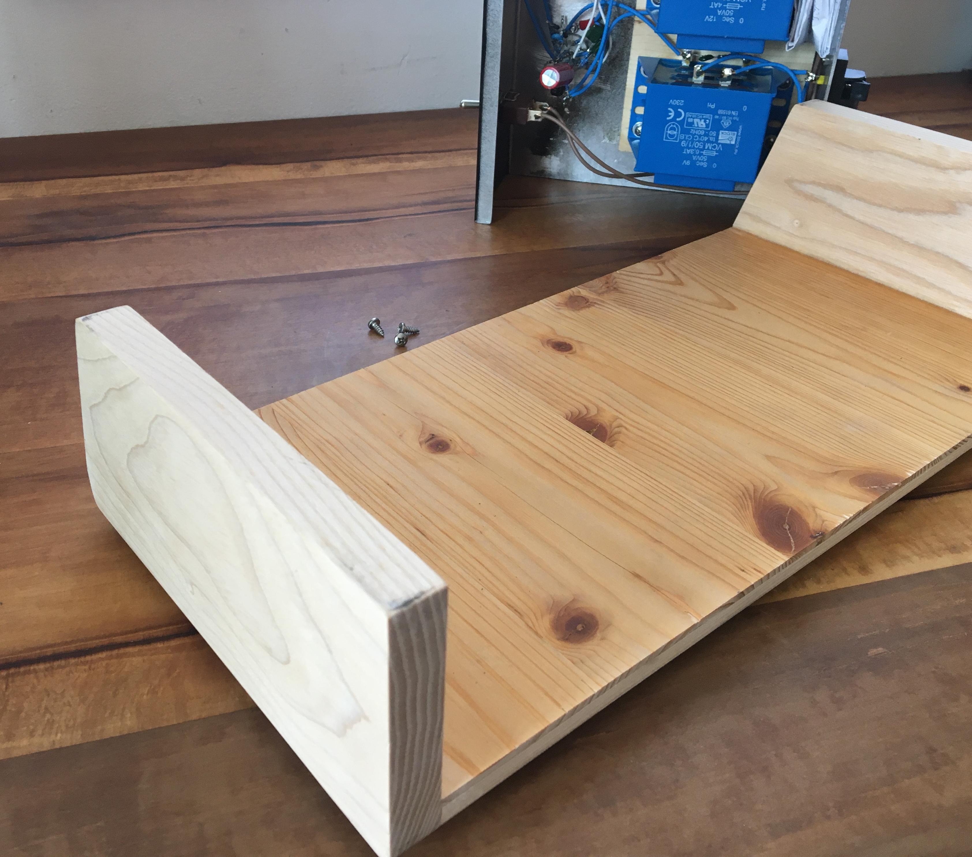
The main part of the mechanical construction is an aluminum sheet metal part. First, I made all the cutouts and drilled all the holes for the mains socket, tube sockets, switch, potentiometer, audio jack, speaker terminals and screws. Then, I made the bents with a sheet metal folder and spray painted the part. The aluminum part is electrically connected to PE via the corresponding pin of the mains socket, which is critical for safety reasons. A wooden board is glued onto the aluminum part. To this board, all the transformers and a small circuit board are mounted with screws.
The aluminum part with all the components mounted to it slides over a wooden frame. Three screws on the back panel hold the two parts securely together.
Electrical Setup
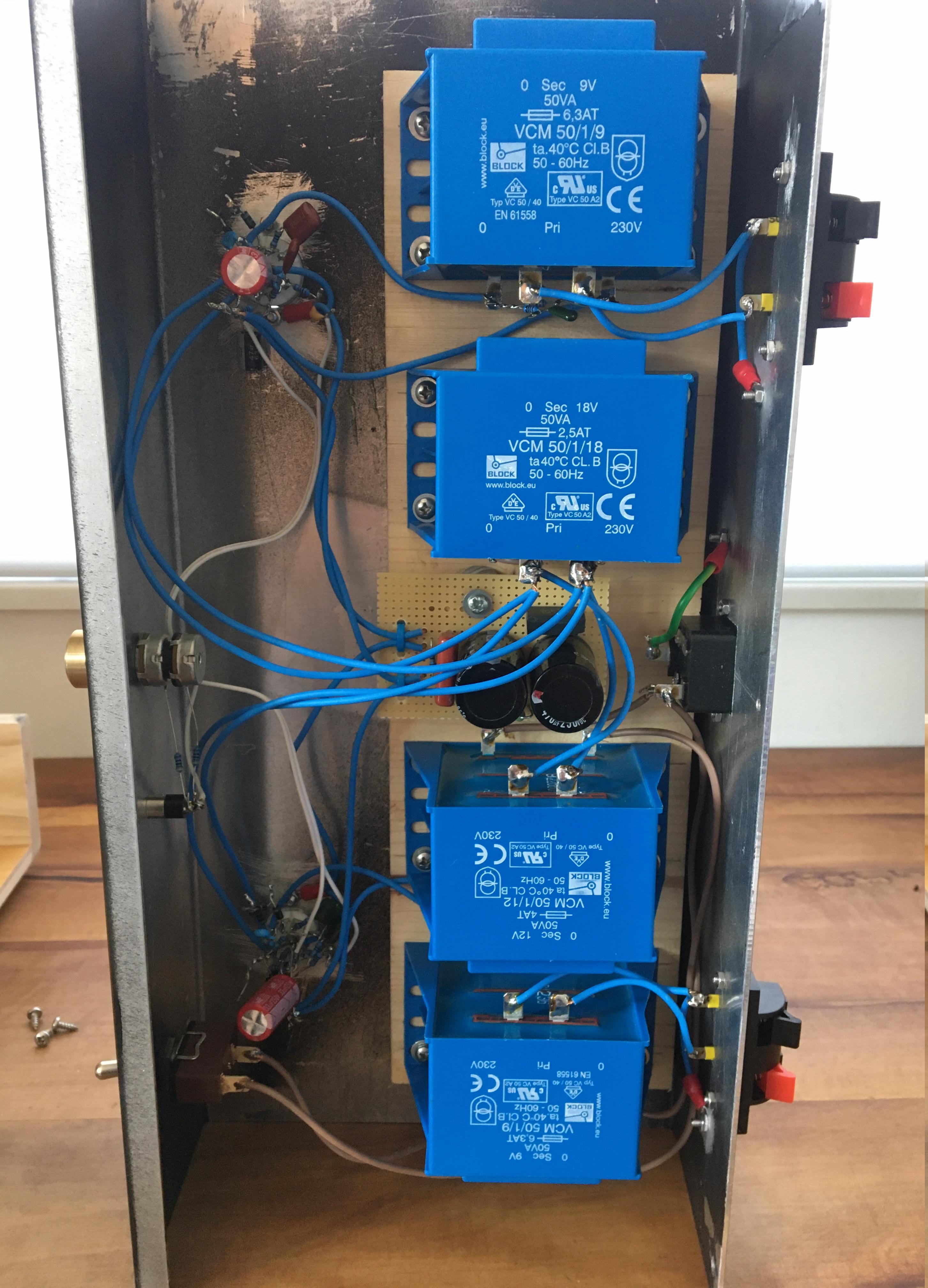
The PCL86 requires an anode voltage of about \(200\,\mathrm{V}\) and the heating filament requires \(13\,\mathrm{V}\). For providing these voltages (at least approximately), two transformers are used, namely a \(230\,\mathrm{VAC}\) to \(12\,\mathrm{VAC}\) transformer and a \(230\,\mathrm{VAC}\) to \(18\,\mathrm{VAC}\) in the following configuration:
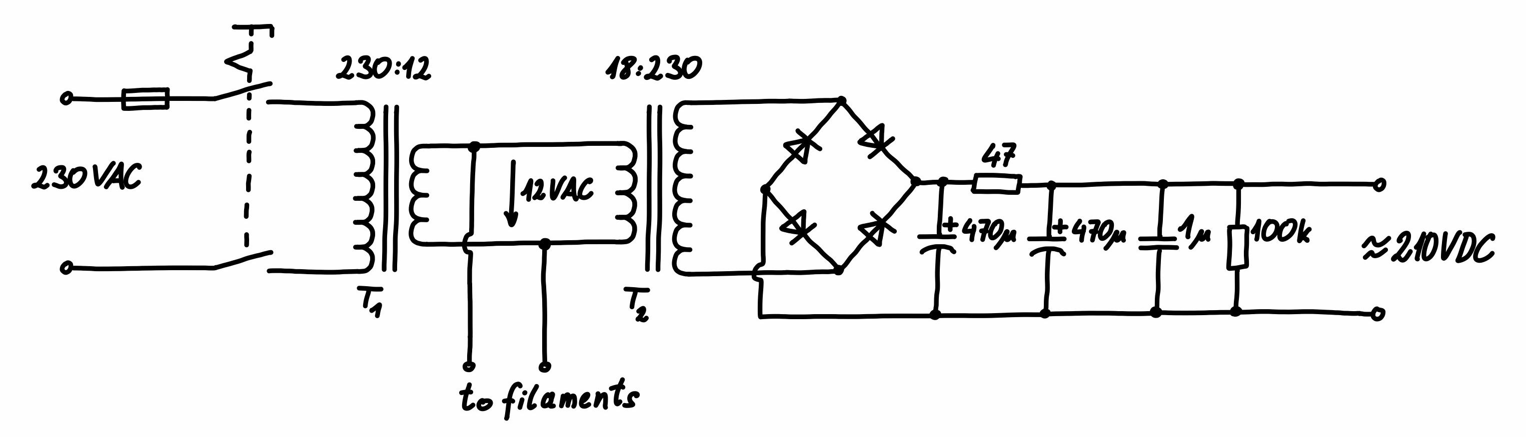
The \(12\,\mathrm{VAC}\) output voltage of the transformer T1 is used for supplying the filaments of the tubes. (Since the transformer is rated for \(50\,\mathrm{VA}\) and it is under relatively light load, its actual output voltage is close to \(13\,\mathrm{VAC}\).) Transformer T2 is intended for transforming \(230\,\mathrm{VAC}\) to \(18\,\mathrm{VAC}\), but here it is hooked up in reverse, to produce approximately \(150\,\mathrm{VAC}\) from \(12\,\mathrm{VAC}\). After rectification and some filtering, this yields approximately \(200\,\mathrm{VDC}\), which is used for supplying the tubes.
The figure below shows the schematic for each of the two amplifier channels. I soldered all the components directly to the tube sockets, i.e. I did not use perfboard here.
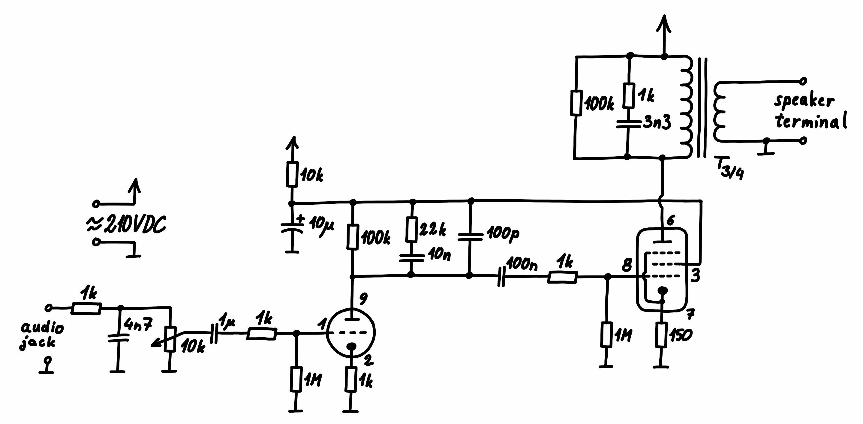
Both, the triode preamplifier and the pentode end amplifier are basic class A common cathode amplifiers. The \(22\,\mathrm{k\Omega}\) resistor and the \(10\,\mathrm{nF}\) and \(100\,\mathrm{pF}\) capacitor in the anode section of the triode are used for shaping the frequency response of the amplifier, together with the \(1\,\mathrm{k\Omega}\) resistor and the \(4.7\,\mathrm{nF}\) capacitor at the input. All these components essentially emphasize low frequencies over high frequencies. This is mandator for an overall flat frequency response in the audible range, because the output transformers do not work great at low frequencies. The output transformers are standard \(230\,\mathrm{VAC}\) to \(9\,\mathrm{VAC}\) mains transformers, intended for \(50\,\mathrm{Hz}\), but not intended for audio applications. These transformers nevertheless work reasonably well up to several \(\mathrm{kHz}\), but they add a relatively high lower cutoff frequency to the output amplifier stage. Emphasizing the low frequencies in the preamplifier stage counteracts this undesired effect of the output transformers.
Since the current through the primary of the output transformers has a DC offset due to the biasing of the output tube, I used large transformers rated for \(50\,\mathrm{VA}\). Although the output power of the amplifier is far from \(50\,\mathrm{W}\) (it actually in the range of \(1\,\mathrm{W}\)), a smaller transformer could saturate due to the DC bias current.
In professional tube amplifiers, special audio transformers are used, which are often the most expensive part of such amplifiers. Those special transformers have a high inductance, which is mandatory for a low cutoff frequency. Additionally, these transformers usually have an air gap in the iron core. This way, these transformers can handle the DC offset current in the primary winding without the core getting into saturation.
The amplifier works well with \(4\,\mathrm{\Omega}\) to \(8\,\mathrm{\Omega}\) speakers. Clean output power is in the range of \(1\,\mathrm{W}\), which is not much, but plenty for home use when speakers of decent quality are used. It is definitely not a Hi-Fi amplifier. Due to the lack of an overall negative feedback loop, the linearity relies on the linearity of the tubes and transformers themselves.